Engineering Standards Guide · ANSI/ESD S20.20-2021
ESD S20.20 Requirements for Electronics Flooring
A complete reference on the ESD S20.20 requirements every floor must satisfy in an electronics manufacturing, semiconductor, PCB assembly, or test environment — resistance limits, body voltage generation, charge decay, grounding architecture, and verification testing. Written for facility engineers, ESD coordinators, and architectural specifiers comparing ESD epoxy flooring, anti static epoxy flooring, and conductive epoxy flooring against full ANSI/ESD S20.20 compliance.
GET A FREE QUOTE

Standard · ANSI/ESD S20.20-2021
Scope · ESDS Class 100V+ (HBM)
Updated · May 2026
PumaESD Product Lineup
What is ANSI/ESD S20.20 — and what does it require of the floor?
ANSI/ESD S20.20-2021(opens in new tab) is the governing U.S. standard for ESD control programs in electronics manufacturing. It is published by the ESD Association(opens in new tab) (EOS/ESD) and is the document virtually every U.S. electronics specifier, contract manufacturer, and DoD program references when writing ESD control requirements.
S20.20 defines the requirements for protecting electrical or electronic parts, assemblies, and equipment susceptible to ESD damage from human body model (HBM) discharges greater than or equal to 100 volts. In plain language: if your facility handles any component that can be damaged by a 100-volt zap, S20.20 is the standard you are designing the floor to. The 2021 edition is the current revision; earlier editions (S20.20-2014, S20.20-2007) remain referenced in legacy contracts.
S20.20 is a performance standard, not a product standard
S20.20 does not specify a flooring product. It specifies performance outcomes — measured resistance, measured body voltage, measured charge decay. The floor manufacturer's job is to deliver a system that meets those outcomes; the facility's job is to test and verify them after install and on an ongoing basis.
What S20.20 requires of the floor
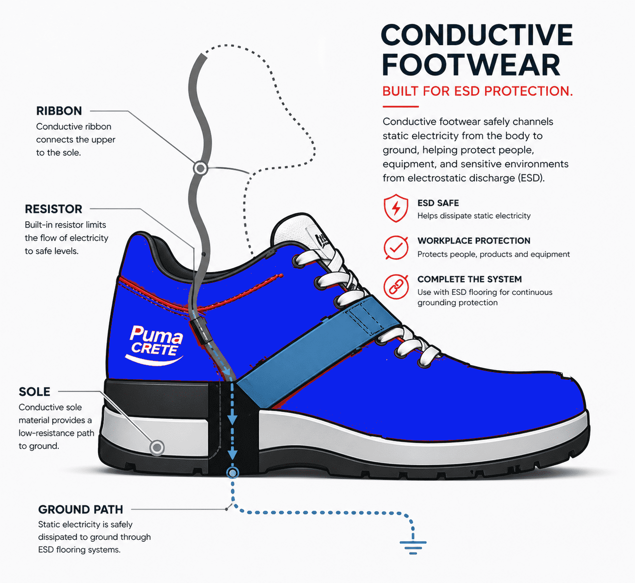
The floor — combined with the operator’s footwear — sits at the center of the S20.20 personnel grounding system. Four requirements apply:
- Limit body voltage generation to under 100 volts when walked upon
- Maintain person + footwear + floor resistance below 3.5 × 10⁷ Ω
- Provide a continuous, verifiable path to ground
- Support periodic compliance verification testing
S20.20 calls out the floor under two scenarios. In the floor + footwear combination scenario (the most common in electronics manufacturing), the floor and ESD-compliant footwear together deliver personnel grounding. In the floor-only scenario, used in some semiconductor and energetics applications, the floor alone must provide the full grounding path. Both scenarios are valid; the choice depends on whether the facility can manuever a strict footwear policy in practice.
S20.20 resistance requirements
Resistance is the most-tested, most-specified, most-misunderstood property of an S20.20-compliant floor. Two ranges matter: the floor on its own (point-to-point and point-to-ground), and the floor as part of the human/footwear system.
S20.20 floor resistance ranges (ohms, log scale)
S20.20 body voltage generation & charge decay
Body voltage generation (BVG) — the 100 V limit
Body voltage generation is the static charge that builds up on a person as they walk across a floor — the property the floor most directly controls. Resistance tells you whether a charge can drain; BVG tells you whether the floor is actually preventing charge from accumulating under normal operator movement. S20.20 references ANSI/ESD STM97.2 for measurement methodology.
S20.20 BVG limit
Less than 100 volts body voltage generated during a defined walking test, measured with the operator’s actual footwear and the actual installed floor.
PumaCRETE PumaESD performance
Less than 15 volts BVG with conductive footwear — approximately an 85% safety margin against the S20.20 ceiling, equal to Sika Sikafloor-200 ESD (15V) and better than Dur-A-Flex Dur-A-Gard ESD (~14V).
Operator footwear is half of the S20.20 equation. A compliant floor under a non-compliant heel strap or street shoe will fail STM97.2 testing. The flooring specification and the footwear policy are written as a single ESD control program system.
Charge decay — the 5,000-volt test
Charge decay measures how fast an existing static charge bleeds off the floor (or off a person standing on it) to ground. The standard reference test charges the surface to 5,000 volts and measures the time to dissipate to zero. To qualify as static dissipative under S20.20: under 2 seconds. To qualify as conductive: under 0.5 seconds.
PumaCRETE PumaESD static dissipative systems dissipate a 5,000-volt charge to zero in under 0.1 seconds — well beyond the minimum S20.20 requires. This margin matters because real-world conditions degrade test-bench performance: humidity changes, contamination, accidental wax application, and floor wear all push decay time upward over the life of the installation.
Why S20.20-compliant conductivity must be built in, not topical
Topical antistatic treatments wear off in weeks under industrial traffic. PumaCRETE uses graphite micro-particles dispersed throughout the resin matrix — the conductive network is integral to the floor and is maintained as the surface wears. Stonhard uses carbon nanotubes in Stonkote ESD; Dur-A-Flex uses carbon dispersion in Armor-Stat ESD. All three approaches keep S20.20 charge decay performance stable for the life of the floor.
S20.20 grounding architecture
S20.20 requires a continuous, verifiable path to ground. Without this connection, the resistance numbers on the data sheet are irrelevant — the floor cannot drain charge.
S20.20 grounding requirements at install
- Conductive copper grounding tape installed under the topcoat
- One ground connection point per 1,000 to 1,500 square feet of floor area
- Ground tape connected to columns, wall studs, or dedicated ground stakes
- Connection terminated to building equipment grounding conductor (EGC)
- Resistance from any floor point to ground verified after installation
- Ground points documented on as-built drawings for verification testing
Where S20.20 grounding most often fails in the field
Grounding failures rarely show up at the grounding hardware itself. They show up at the boundary — where new ESD flooring meets an unprepared substrate, where ground tape was cut during a later renovation, where building ground has degraded, or where a coating contractor installed the topcoat over uncured or unprimed grounding strips.
This is one of the principal reasons PumaCRETE installations are completed by factory-trained certified applicators. S20.20 electrical performance written on the data sheet only survives the field if install discipline matches the formulation.
Adjacent and related standards
S20.20 is the anchor. Depending on the facility, the floor may also need to satisfy the following standards — referenced either inside the S20.20 framework (test methods) or as parallel compliance requirements.
| Standard | Scope | Relationship to S20.20 |
|---|---|---|
| ANSI/ESD STM7.1 | Resistance characterization of floor materials | Test method referenced by S20.20 |
| ANSI/ESD STM97.1 | Resistance measurement with footwear | Test method referenced by S20.20 |
| ANSI/ESD STM97.2 | Body voltage measurement with footwear | Test method referenced by S20.20 |
| IEC 61340-5-1 | International ESD control standard | Harmonized with S20.20 |
| NFPA 99 | Anesthetizing locations, healthcare | Parallel compliance for medical / hospital ESDS areas |
| DoD 4145.26-M | Munitions, energetics, explosives | Parallel compliance — conductive flooring required |
| ASTM F150 | DC resistance of conductive flooring | Companion test method |
For pure electronics manufacturing, S20.20 alone is sufficient. For mixed-use facilities — a contract manufacturer that also handles energetics, for example — the floor must meet the strictest applicable standard. PumaCRETE 300/400 Series PumaESD systems are written to meet S20.20, NFPA 99, and DoD 4145.26-M simultaneously for facilities that need single-source compliance across multiple standards.
S20.20-compliant floors compared — PumaCRETE vs. Stonhard, Sika, Dur-A-Flex, Florock
All major ESD epoxy manufacturers meet the baseline of ANSI/ESD S20.20. The real differentiation between S20.20-compliant systems is in substrate condition tolerance, moisture vapor handling, renovation capability, and the durability range of available system tiers. Here is how PumaESD compares on the technical points electronics specifiers care about most.
| Property | PumaCRETE PumaESD | Stonhard Stonshield ESD | Sika Sikafloor-200 ESD | Dur-A-Flex Dur-A-Gard ESD | Florock ESD |
|---|---|---|---|---|---|
| S20.20-2021 compliance | Yes | Yes | Yes | Yes | Yes |
| Resistance range (Ω) | 10⁶–10⁹ (-d) / 2.5×10⁴–10⁶ (-c) | 10⁶–10⁹ | 10⁶–10⁹ | 10⁶–10⁹ | 10⁴–10⁶ / 10⁶–10⁹ |
| Body voltage generation | < 15 V | Class 0 capable | < 15 V | ~14 V | Compliant |
| Charge decay (5kV → 0V) | < 0.1 s | S20.20 compliant | S20.20 compliant | S20.20 compliant | S20.20 compliant |
| Conductive mechanism | Graphite throughout matrix | Carbon nanotubes / through-system | Conductive fillers | Carbon dispersion | Conductive primer + carbon |
| Moisture vapor tolerance | Up to 25 lb (104-MB primer) | 3 lb / requires MVT primer | 3 lb / requires primer | 3 lb | 3 lb |
| Renovation of damaged concrete | Yes — 300/400 Series resurface | HRI Base patching | Primer + patching | Patching prior | Patching prior |
| Heavy-duty urethane topping | Yes — 400 Series, 1/4″–3/4″ | Stonclad ESD 6 mm | None at this thickness | None at this thickness | None at this thickness |
| S20.20 + NFPA 99 + DoD 4145.26-M | Yes | Yes | Yes | Limited | Limited |
| Maintenance — no wax, no re-coat | Yes | Yes | Yes | Yes | Yes |
Sources: Stonhard ESD Flooring(opens in new tab) · Sikafloor-200 ESD product data(opens in new tab) · Dur-A-Flex Dur-A-Gard ESD(opens in new tab) · Florock ESD & Conductive Flooring(opens in new tab) · ESD Association — ANSI/ESD S20.20(opens in new tab). Specifications current as of Q2 2026; verify with manufacturer technical data sheets before specification.
Where PumaCRETE wins on S20.20 compliance
Substrate condition range and moisture vapor tolerance. Most S20.20-compliant epoxy systems require new or like-new concrete and cap out at 3 lb MVER. PumaCRETE 300/400 Series resurfaces deteriorated, spalled, or cracked slabs in renovation while delivering full S20.20 performance, and the optional 104-PumaPOXY MB moisture blocker handles up to 25 lb MVER — making PumaESD the right S20.20 specification for ground-floor and below-grade electronics facilities where competitors require slab replacement.
PumaESD systems that meet S20.20 & verification testing
PumaESD is PumaCRETE’s complete line of S20.20-compliant ESD and conductive epoxy flooring systems spanning the 100 to 400 Series. Every tier is available in static dissipative (-d) or conductive (-c) versions, with a four-component chemical-resistant aliphatic polyester ESD urethane top coat standard across the line.
| System | Build & thickness | Best for | Substrate condition | Standards met |
|---|---|---|---|---|
| 100 Series | Thin-film coating (12–20 mils) | Light-duty assembly, test benches, controlled spaces | New or like-new concrete | S20.20 |
| 200-d / 200-c | Hi-build roll-on coating (12–20 mils) | Data centers, electronics manufacturing, cleanroom-adjacent | New or good condition concrete | S20.20, NFPA 99 |
| 201-d / 201-c | Hi-build coating (~43 mils) | Fair concrete needing hiding power; medium-traffic | Fair concrete with minor defects | S20.20, NFPA 99 |
| 301-SLB PumaESD | Slurry urethane (1/16″–1/4″) | Heavy-traffic manufacturing, AGV/AMR corridors, renovation | Worn, cracked, or damaged concrete | S20.20, DoD 4145.26-M, NFPA 99 |
| 401-HF PumaESD | Heavy-duty trowel/screed (1/4″–3/4″) | Most demanding traffic, forklifts, hardest-wear environments | Any condition (resurfaces) | S20.20, DoD 4145.26-M, NFPA 99 |
System tier selection depends less on the S20.20 electrical class — set by the application — and more on substrate condition, traffic loading, and whether the install is new construction or renovation. See the full MasterFormat specifications and system features overview for technical data sheets.
S20.20 verification testing
A floor that is not tested is not S20.20 compliant. The standard requires a documented Compliance Verification Plan covering both initial qualification and periodic re-test.
At installation — qualification testing
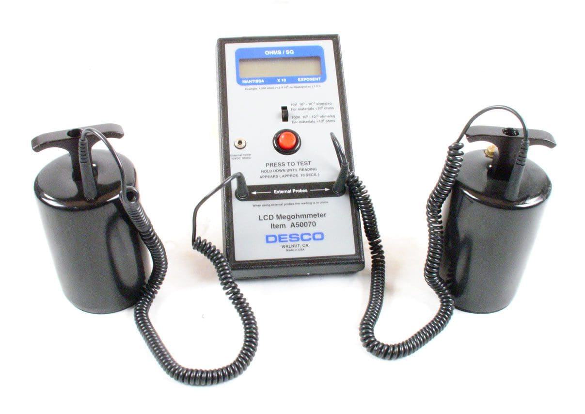
- Resistance point-to-point per ANSI/ESD STM7.1
- Resistance point-to-ground at every grounded location
- System resistance with footwear per ANSI/ESD STM97.1
- Body voltage generation per ANSI/ESD STM97.2
- Visual inspection of grounding terminations
- Documented baseline report retained on file
During service life — ongoing verification
Periodic re-test on a quarterly or annual basis depending on traffic and contamination risk. The test grid is referenced to the as-built ground point drawing so results are comparable over time. Drift toward the upper S20.20 resistance limit is the leading indicator of contamination — usually from improper cleaning products, applied wax, or accumulated process residue.
Cleaning matters more for S20.20 compliance than people expect
Do not wax. Do not use solvent-based or oily cleaners. Use a neutral-pH ESD-safe cleaner and a clean mop head. The wrong cleaner is the most common cause of an otherwise-compliant floor failing S20.20 verification two years after install.
Industry sectors for ESD flooring:
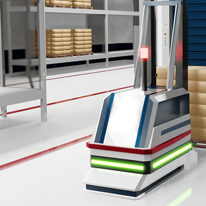
AGV ROBOT AREAS

ELECTRONICS MANUFACTURING
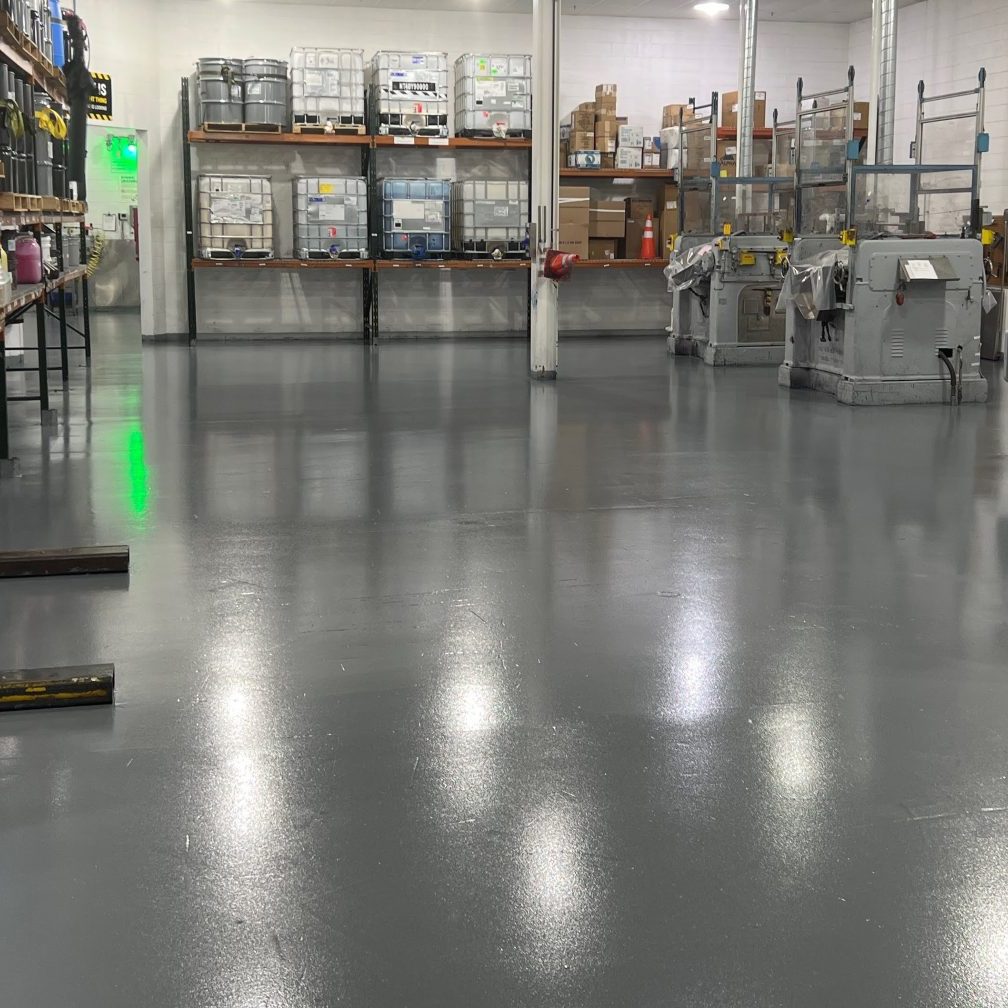
AMMUNITION / EXPLOSIVES

DATA NETWORK CENTERS
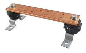
EARTH GROUND (copper ground rod, bar, outlet.
Copper ground rods are often used in Military, Munitions, and manufacturing environments. At the ground point on rod... remove oxidation from rod (for connection with a clamp). Run copper foil tape on the floor, per figure 2. Run the tape up the ground rod, and secure tape to ground rod using the copper foil tape.
Certify the Flooring meets:
DoD 4145.26M(opens in new tab) ESD Association S20.20(opens in new tab) NFPA(opens in new tab) OSHA(opens in new tab)
Certify the Flooring meets:
DoD 4145.26M(opens in new tab) ESD Association S20.20(opens in new tab) NFPA(opens in new tab) OSHA
Frequently Asked Questions
Related resources, frequently asked questions & next steps
ESD & Conductive Floors
Full line of PumaESD systems — dissipative and conductive options
ESD Epoxy for Electronics Manufacturing
SMT, PCB assembly, semiconductor, and inspection area applications
Conductive Epoxy Flooring
2.5 × 10⁴ to 10⁶ Ω systems for energetics and AGV/AMR corridors
Data Center Anti-Static Floors
200 Series roll-on coating system for server halls and NOC facilities
AGV & AMR Flooring
301-AGV PumaESD with COF > 0.6 and DIN EN 61340-5-1 compliance
MasterFormat Specifications
Architect-ready specs for the 200, 300, and 400 PumaESD Series
Static dissipative (ESD) flooring has electrical resistance between 1×10&sup6; and 1×10&sup9; ohms — high enough to safely bleed off static but low enough to prevent dangerous discharge. Conductive flooring has lower resistance (25,000 to 1 million ohms) and dissipates charges faster. Dissipative is for electronics; conductive is required for munitions and AA&E under DoD 4145.26-m.
Yes. PumaCRETE offers three buying options: complete turnkey installation through our nationwide network of certified applicators, materials-only supply if you have your own crew or contractor, or on-site factory training to qualify your own installers. Specify the model that fits your project.
Yes. PumaCrete™ cures to a 100% seamless, non-porous surface that inhibits fungal and bacterial growth. It fully complies with USDA, FDA, CFIA, and OSHA requirements for safe food processing and sanitary environments.
PumaCRETE ESD flooring uses graphite micro-particles built into the floor matrix that maintain conductive properties for the life of the product. No wax, no topical treatment, no recoating required.
Electronics manufacturing, PCB assembly, semiconductor fabrication, data centers, AGV and AMR corridors, munitions and AA&E facilities, aerospace and defense, pharmaceutical cleanrooms, biotech, medical device manufacturing, and any facility handling ESD-sensitive components or flammable solvents.
Yes. Every PumaCRETE turnkey installation includes post-install resistance testing and grounding verification. Written documentation of ANSI/ESD S20.20 or DoD 4145.26-m compliance is provided, suitable for facility audits.
PumaCRETE installs ESD and conductive flooring nationwide through a network of factory-trained certified installer partners. Major regional coverage includes Massachusetts, Connecticut, and New York — see our dedicated state pages for region-specific details. Materials-only supply and factory training options are available in all 50 states.
EXPERIENCE AND EXPERTISE
THE PumaCRETE Difference
We have over 30 years of experience behind us. Customers can rest assure that the system we recommend shall be the most cost effective. We provide customized solutions for challenging issues.
