Military Specification Guide · DoD 4145.26-M · ANSI/ESD S20.20
DoD Military Standards for Conductive Flooring
A complete reference on the DoD military standards for conductive flooring in ammunition, explosives, propellant, energetics, and electronics facilities — covering DoD 4145.26-M (DoD Contractors’ Safety Manual for Ammunition and Explosives), DoD 6055.9-STD, the canceled MIL-STD-1686 series, its replacement by ANSI/ESD S20.20, and the now-outdated status of NFPA 99 for ESD flooring. Written for DoD contractors, AA&E facility engineers, ESD coordinators, and architectural specifiers.
GET A FREE QUOTE

Primary Standard · DoD 4145.26-M (March 13, 2008)
Scope · AA&E facilities + ESDS electronics
PumaESD Product Lineup
DoD 4145.26-M overview & AA&E scope
DoD 4145.26-M(opens in new tab), dated March 13, 2008, is the DoD Contractors’ Safety Manual for Ammunition and Explosives. It is the primary U.S. military standard governing safety in any AA&E (Arms, Ammunition, and Explosives) facility operated by a DoD contractor, subcontractor, or supplier — and the document that controls conductive flooring specifications in those environments.
4145.26-M establishes safety standards common to DoD and private industry ammunition and explosives operations, facilities, and services performed under DoD contracts, subcontracts, purchase orders, and other procurement methods. DoD 6055.9-STD serves as the primary source document — 4145.26-M draws its safety standards from 6055.9-STD and translates them into the contractor-facing manual.
Section C6.4 — Static Electricity and Grounding is the operative chapter for flooring. Within C6.4, the two subsections that govern floor electrical performance are C6.4.7.5.1 (maximum resistance test criteria) and C6.4.7.5.2 (minimum resistance for electrocution protection) — covered in detail in the next section.
Who must comply with DoD 4145.26-M
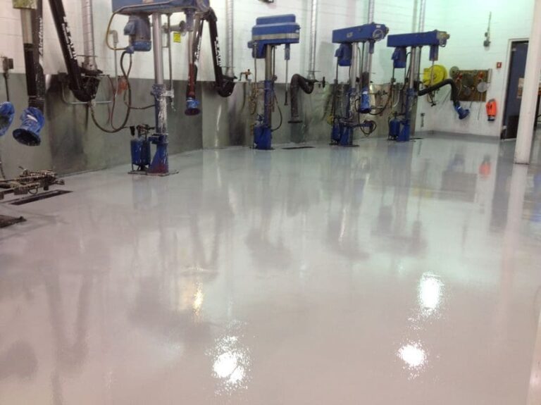
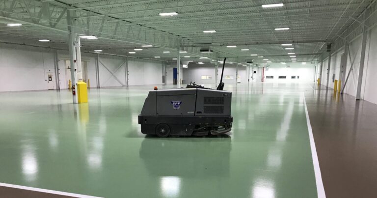
Any contractor, subcontractor, or facility operator performing AA&E work under a DoD contract must comply with 4145.26-M. This covers:
- Ammunition manufacturing and load-assemble-pack (LAP) facilities
- Explosives processing, mixing, and storage
- Propellant manufacturing and casting operations
- Pyrotechnic and energetics assembly lines
- Missile and rocket motor production
- Ammunition warehouses serving DoD contracts
- Demilitarization and disposal operations
- Testing facilities handling live ordnance
Why conductive flooring is mandatory in AA&E areas
Energetic materials — primary explosives, propellants, pyrotechnics, certain secondary explosives — can be initiated by a static discharge as low as a few millijoules. A person walking across a conventional floor generates tens of thousands of volts of static charge. In an AA&E facility, that’s not a productivity problem; it’s an ignition source. Conductive flooring continuously drains charge to ground before it can accumulate to dangerous levels.
DoD 4145.26-M electrical requirements — deep dive
DoD 4145.26-M Section C6.4.7.5 sets both an upper and a lower bound on floor electrical resistance. The upper bound exists for static control. The lower bound exists for personnel electrocution protection. Both must be satisfied simultaneously — the compliant range is the window between them.
DoD 4145.26-M compliant resistance window (ohms, log scale)
Below minimum — electrocution hazard
C6.4.7.5.1 — Test Criteria (maximum resistance)
Per Section C6.4.7.5.1 of DoD 4145.26-M: “The contractor can set the maximum resistance limits for the floor to the ground system and for the combined resistance of a person’s body plus the shoes, as long as the total resistance does not exceed 1,000,000 ohms (1.0 × 10⁶).”
In plain language: the entire grounding path — person + footwear + floor + ground connection — must measure under 1 megohm. This is the value that drives the choice between conductive (10⁴–10⁶ Ω) and static dissipative (10⁶–10⁹ Ω) flooring. Static dissipative floors do not satisfy the 4145.26-M ceiling because the floor alone can already exceed 1 megohm before footwear and body resistance are added.
C6.4.7.5.2 — Minimum Resistance (electrocution protection)
Per Section C6.4.7.5.2: “To protect against electrocution, the minimum resistance of the floor to the ground system shall exceed 40,000 ohms (4.0 × 10⁴) in areas with 110 volts service and 75,000 ohms (7.5 × 10⁴) in areas with 220 volts service.”
This lower bound is the reason DoD 4145.26-M conductive flooring is not truly conductive — it is highly conductive within a controlled window. A bare-metal or zero-resistance path to ground would protect against ESD ignition but would create a direct shock path if a person in contact with the floor also contacted line voltage. The 40k / 75k Ω minimums limit the maximum current that could flow through a person under fault conditions while still draining static charge fast enough to prevent ignition.
Important boundary — MIL-STD-1686 / S20.20 does not cover AA&E
Both MIL-STD-1686 and ANSI/ESD S20.20 explicitly exclude electrically initiated explosive devices and AA&E areas. The governing standard for those facilities is DoD 4145.26-M, not S20.20. Mixed-use facilities — for example, an electronics contractor that also packages or stores energetics — must comply with both: S20.20 in the electronics zones and 4145.26-M in the AA&E zones. The stricter of the two applies in any overlap area.
NFPA 99 status & adjacent military standards
NFPA 99 — no longer a conductive flooring standard
NFPA 99(opens in new tab) (“Health Care Facilities Code”) historically established criteria for health-care facilities to minimize hazards of fire, explosion, and electricity, including requirements for conductive flooring in anesthetizing locations.
In 2015, the NFPA eliminated conductive flooring requirements from NFPA 99 — modern volatile anesthetic agents are no longer flammable, removing the original justification for mandatory conductive floors in operating rooms. This makes NFPA 99 an outdated reference for new conductive or ESD flooring specifications.
egacy specifications still calling out NFPA 99
Older architectural specs, contracts, and procurement documents may still reference NFPA 99 for conductive flooring. These specifications should be reviewed and updated to reference DoD 4145.26-M (AA&E facilities) or ANSI/ESD S20.20 (electronics) as appropriate. A modern PumaCRETE conductive system meeting DoD 4145.26-M will satisfy any residual NFPA 99 conductivity requirement by margin.
Adjacent and supporting military / ESD standards
Several standards sit alongside DoD 4145.26-M and ANSI/ESD S20.20, either as test methods, parallel requirements, or supporting references.
| Standard | Scope | Status / Relationship |
|---|---|---|
| DoD 4145.26-M | Contractor AA&E safety manual | Active — March 13, 2008 |
| DoD 6055.9-STD | DoD Ammunition & Explosives Safety Standards | Active — primary source for 4145.26-M |
| MIL-STD-1686C | ESD Control Program (electronics) | Canceled 12 January 2021 |
| ANSI/ESD S20.20 | ESD Control Program (electronics) | Active — DoD-adopted replacement for MIL-STD-1686 |
| ANSI/EIA-625 | Electronics handling ESD control | Superseded by ANSI/ESD S20.20 |
| ANSI/ESD STM7.1 | Resistance characterization of floor materials | Test method — referenced by S20.20 |
| ANSI/ESD STM97.1 | System resistance with footwear | Test method — referenced by S20.20 |
| ANSI/ESD STM97.2 | Body voltage with footwear | Test method — referenced by S20.20 |
| NFPA 99 | Health-care facility code (anesthetizing) | Conductive flooring eliminated 2015 |
| IEC 61340-5-1 | International ESD control standard | Active — harmonized with S20.20 |
| ASTM F150 | DC resistance of conductive flooring | Active — companion test method |
For DoD contracts, the controlling document is DoD 4145.26-M (or 6055.9-STD by reference) for AA&E areas, and ANSI/ESD S20.20 for electronics. NFPA 99 should not be specified for new construction.
Conductive vs. dissipative — which DoD applications
The most important specification decision in DoD flooring is the choice between conductive (C) and static dissipative (SD). They are not interchangeable. The decision is driven by the applicable standard (4145.26-M vs. S20.20) and the materials being handled, not by traffic or aesthetics.
| Property | Conductive (C) | Static Dissipative (SD) |
|---|---|---|
| Floor resistance range | 2.5 × 10⁴ – 1.0 × 10⁶ Ω | 1.0 × 10⁶ – 1.0 × 10⁹ Ω |
| Governing DoD standard | DoD 4145.26-M | ANSI/ESD S20.20 (electronics) |
| Total system maximum | < 1.0 × 10⁶ Ω | < 3.5 × 10⁷ Ω |
| Charge dissipation speed | Fastest possible — under 0.5 s | Controlled — under 2.0 s |
| Ammunition & explosives (AA&E) | Required | Does not satisfy 4145.26-M |
| Energetics, pyrotechnics, propellants | Required | Does not satisfy 4145.26-M |
| Flammable solvent / vapor processing | Recommended | Acceptable with risk review |
| Electronics manufacturing (SMT, PCB) | Acceptable | Standard specification |
| Semiconductor fabrication | Application-specific | Standard specification |
| AGV / AMR corridors | Recommended for vehicle ESD | Acceptable |
| Data centers, server rooms | Optional | Standard specification |
| Personnel shock hazard at line voltage | Mitigated by DoD min resistance | Inherently low risk |
Specify conductive (C) when…
…the facility handles AA&E materials governed by DoD 4145.26-M, or when the rate of charge dissipation is the safety-critical variable. The C designation is mandatory in ammunition LAP, explosives processing, propellant casting, pyrotechnic assembly, energetics manufacturing, and any DoD AA&E storage covered by 6055.9-STD.
Specify static dissipative (SD) when…
…the facility is governed by ANSI/ESD S20.20 and the priority is protecting ESDS components from human-body-model discharges without the higher conductivity needed for energetics. SD is the correct choice for SMT lines, PCB assembly, semiconductor fab, microelectronics, data centers, and general electronics manufacturing.
The most common specification mistake in mixed-use facilities
Specifying a single SD floor across a building that contains both an electronics area and an AA&E area. The SD floor will pass S20.20 in the electronics zone and fail 4145.26-M in the AA&E zone. Mixed-use facilities require zoned flooring — conductive (C) where 4145.26-M applies, static dissipative (SD) where S20.20 applies — with a defined transition at the zone boundary.
PumaCRETE conductive systems compliance matrix
PumaCRETE manufactures a complete line of conductive (-c) and static dissipative (-d) epoxy and urethane flooring systems specified for AA&E, electronics, AGV/AMR, and data center applications. The conductive (-c) versions are formulated to a target resistance below 300,000 ohms — a 3.3× safety factor under the DoD 4145.26-M ceiling of 1.0 × 10⁶ Ω, with enough headroom above the 40k/75k Ω electrocution minimums to protect personnel.
Every PumaCRETE conductive system features a four-component, chemical-resistant, aliphatic polyester ESD urethane top coat. Conductive properties come from graphite micro-particles dispersed throughout the resin matrix — not from a topical treatment that wears off. Electrical performance is maintained for the life of the floor.
| System | Build & thickness | Best for | Substrate condition | Standards met |
|---|---|---|---|---|
| 100-c PumaESD | Thin-film coating (12–20 mils) | Light-duty AA&E storage, controlled-traffic areas | New or like-new concrete | DoD 4145.26-M |
| 200-c PumaESD | 3-coat anti-static coating system (12–20 mils) | Ammunition storage warehouses, light AA&E processing | New or good condition concrete | DoD 4145.26-M, ANSI/ESD S20.20 |
| 201-c PumaESD | 4-coat high-build coating (~43 mils) | Fair concrete needing hiding power; medium-traffic AA&E | Fair concrete with minor defects | DoD 4145.26-M, ANSI/ESD S20.20 |
| 301-c PumaESD | Heavy-duty anti-static resurfacer (1/8″–3/16″) | Energetics processing, propellant areas, heavy AA&E traffic | Worn, cracked, or damaged concrete | DoD 4145.26-M, ANSI/ESD S20.20 |
| 301-c AGV PumaESD | Anti-static resurfacer for AGV/AMR (1/8″–3/16″) | AA&E facilities with automated material handling | Any condition (resurfaces) | DoD 4145.26-M, DIN EN 61340-5-1 |
Why substrate condition tolerance matters for DoD work
Many AA&E facilities operate in legacy government buildings — depots, arsenals, and contractor plants where the concrete substrate is decades old, has seen heavy loading, and may have spalled, cracked, or moisture-affected areas. Standard ESD coating systems require new or like-new concrete; a deteriorated substrate forces a slab replacement before installation, multiplying cost and schedule.
PumaCRETE 301-c PumaESD and other resurfacer systems are designed to be installed directly over worn, cracked, and spalled concrete while still delivering full DoD 4145.26-M performance. The optional 104-PumaPOXY MB moisture blocker handles slab moisture up to 25 lb / 1,000 sqft / 24 hr — far above the 3 lb cap of most competing systems — which matters in ground-floor and below-grade AA&E facilities where slab moisture is difficult to remediate.
Sources: DoD 4145.26-M (March 13, 2008)(opens in new tab) · MIL-STD-1686C Notice 1 (12 January 2021)(opens in new tab) · ESD Association — ANSI/ESD S20.20(opens in new tab) · MIL-STD-1686 reference(opens in new tab).
Important boundary — MIL-STD-1686 / S20.20 does not cover AA&E
Both MIL-STD-1686 and ANSI/ESD S20.20 explicitly exclude electrically initiated explosive devices and AA&E areas. The governing standard for those facilities is DoD 4145.26-M, not S20.20. Mixed-use facilities — for example, an electronics contractor that also packages or stores energetics — must comply with both: S20.20 in the electronics zones and 4145.26-M in the AA&E zones. The stricter of the two applies in any overlap area.
Specification, installation, grounding & verification
A conductive floor that meets DoD 4145.26-M on the data sheet but fails in the field is a non-compliant facility — and a safety hazard. Installation discipline, grounding architecture, and verification testing are equal partners to the formulation itself.
Specifying a DoD 4145.26-M conductive floor
A complete DoD-compliant flooring specification names all of the following — leaving any one out makes the spec unenforceable:
- Governing standard (DoD 4145.26-M, citing the section)
- Total system resistance range (e.g., 40k–1M Ω per C6.4.7.5)
- Floor electrical class (conductive,
-c) - System thickness and build (mils or fractional inch)
- Substrate preparation requirements (CSP profile)
- Moisture vapor mitigation if applicable (MVER limits)
- Grounding tape spacing and connection requirements
- Acceptance test plan and acceptance criteria
- Ongoing verification schedule and test methods
Cleaning a DoD 4145.26-M conductive floor
Use neutral-pH ESD-safe cleaners only. Do not wax. Do not use solvent-based, oily, or silicone-containing products. Wax in particular will defeat the conductive properties and cause the floor to fail acceptance testing — a finding that can mean a stop-work order in an active AA&E facility until the surface is remediated. Train every cleaning crew member, and post cleaner restrictions on the wall in any conductive area.
Grounding architecture
A conductive floor without a verified path to building ground is dead weight — exactly as if the floor were a standard non-conductive coating. After installation is complete, the new flooring is grounded using conductive copper tape adhered under the topcoat and terminated to a designated ground point at columns, wall studs, or dedicated ground stakes. Industry practice is one ground point per 1,000 to 1,500 square feet of floor area, but a DoD spec may tighten this further. Each ground point is recorded on as-built drawings so verification testing can refer to a documented test grid.
Acceptance testing at installation
DoD 4145.26-M does not specify a single test method, leaving the contractor to select an appropriate one. Industry practice for AA&E flooring uses ASTM F150 (“Standard Test Method for Electrical Resistance of Conductive and Static Dissipative Resilient Flooring”) or the ESD Association’s STM7.1 / STM97.1. The acceptance package typically includes:
- Point-to-point resistance grid per ASTM F150 or STM7.1
- Point-to-ground resistance at every grounded location
- Total system resistance with footwear (STM97.1) at sample stations
- Documented baseline report retained on file
- Visual inspection of all grounding terminations
- Verification that no measured location exceeds 1.0 × 10⁶ Ω
- Verification that no location falls below the 110V / 220V minimums
Ongoing verification during service life
A compliant DoD AA&E facility re-tests floor resistance on a schedule documented in the facility’s safety plan — typically quarterly or annually depending on traffic, contamination risk, and operations. Drift upward toward the 1 megohm ceiling indicates contamination — usually applied wax (do not wax a conductive floor), solvent-based cleaners, or process residue. Drift downward toward the electrocution minimums is rare but can occur near grounding terminations where conductive material may have migrated.
Industry sectors for ESD flooring:

AGV ROBOT AREAS

ELECTRONICS MANUFACTURING
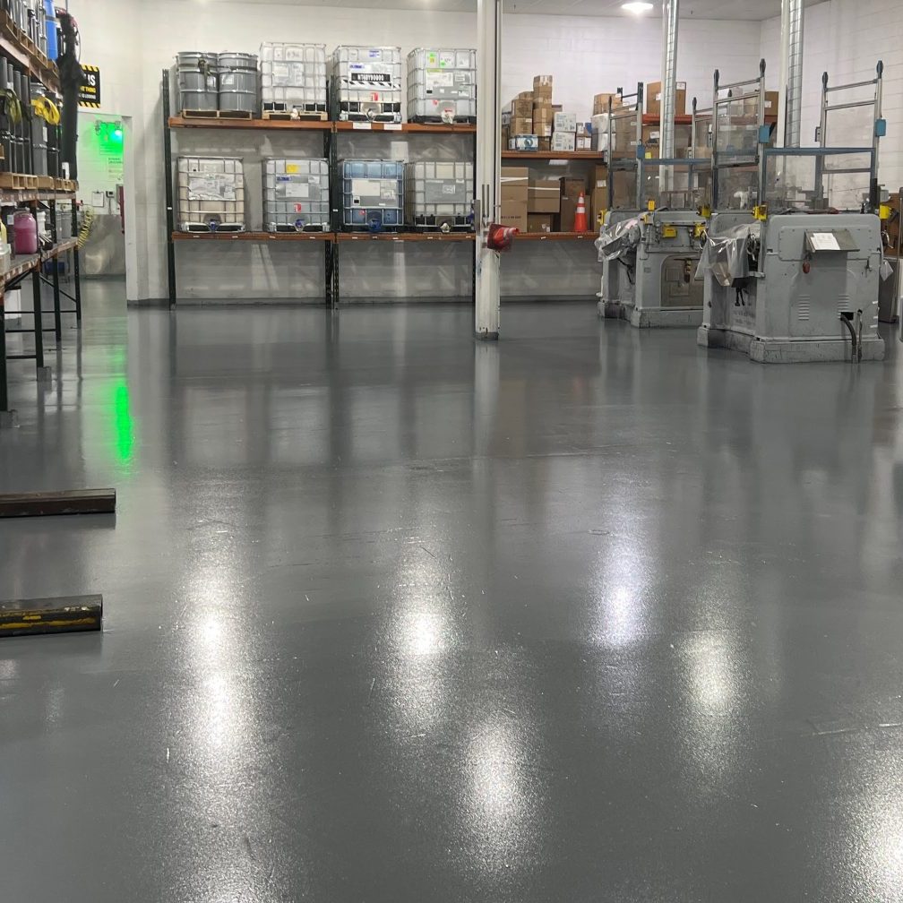
AMMUNITION / EXPLOSIVES

DATA NETWORK CENTERS
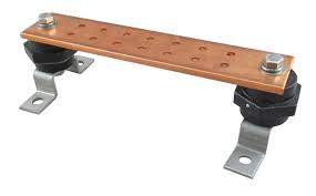
EARTH GROUND (copper ground rod, bar, outlet.
Copper ground rods are often used in Military, Munitions, and manufacturing environments. At the ground point on rod... remove oxidation from rod (for connection with a clamp). Run copper foil tape on the floor, per figure 2. Run the tape up the ground rod, and secure tape to ground rod using the copper foil tape.
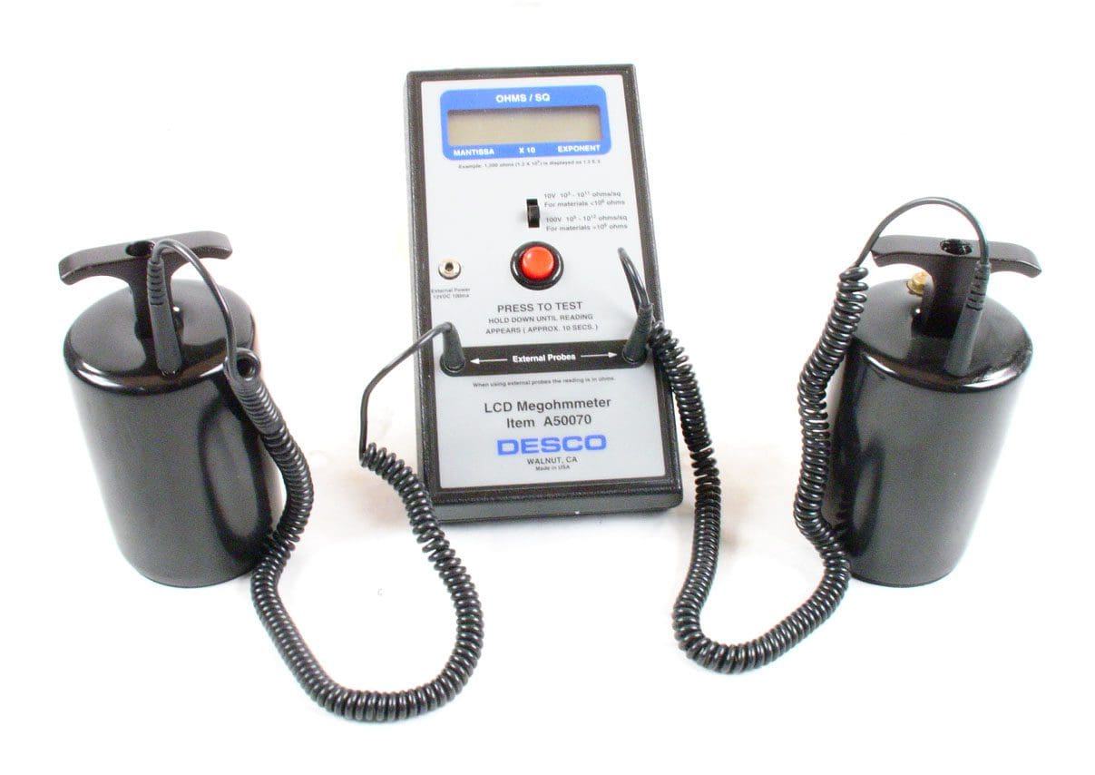
Certify the Flooring meets:
DoD 4145.26M(opens in new tab) ESD Association S20.20(opens in new tab) NFPA(opens in new tab) OSHA(opens in new tab)
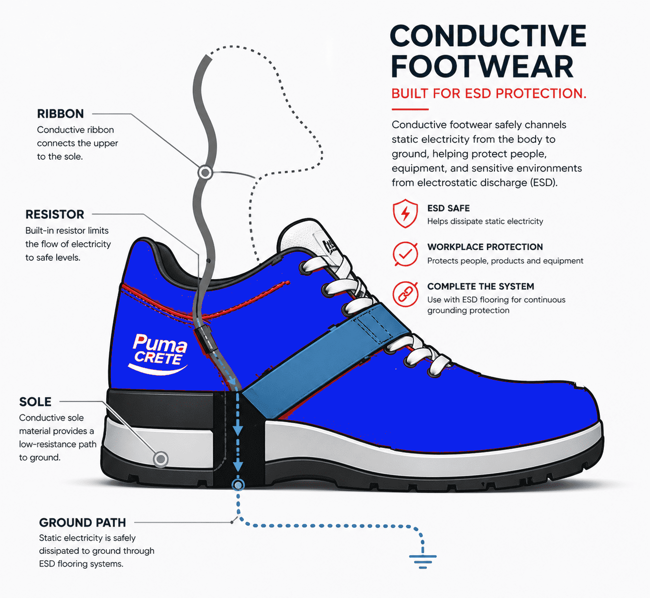
Certify the Flooring meets:
DoD 4145.26M(opens in new tab) ESD Association S20.20(opens in new tab) NFPA(opens in new tab) OSHA
Frequently Asked Questions
Related resources, frequently asked questions & next steps
Related conductive & ESD flooring resources
Continue with related PumaCRETE technical guides and application-specific pages:
Conductive Epoxy Flooring
2.5 × 10⁴ to 10⁶ Ω systems engineered for AA&E applications
ESD & Conductive Floors
Full PumaESD line — both conductive and dissipative options
ESD Epoxy for Electronics Manufacturing
ANSI/ESD S20.20 systems for SMT, PCB, semiconductor, and inspection
AGV & AMR Flooring
301-AGV PumaESD with COF > 0.6 and DIN EN 61340-5-1 compliance
Data Center Anti-Static Floors
200 Series roll-on coating systems for server halls and NOC facilities
MasterFormat Specifications
Architect-ready specs for the 200, 300, and 400 PumaESD Series
DoD 4145.26-M, dated March 13, 2008, is the DoD Contractors' Safety Manual for Ammunition and Explosives. It establishes safety standards for DoD and private industry ammunition and explosives operations and facilities performing AE work under DoD contracts. DoD 6055.9-STD is the primary source document on which DoD 4145.26-M is based.
Per DoD 4145.26-M Section C6.4.7.5.1, the total resistance of a person plus footwear plus floor to ground cannot exceed 1,000,000 ohms (1.0 × 10⁶ Ω, or 1 megohm). PumaCRETE conductive epoxy systems are specified to under 300,000 ohms — a 3.3× safety factor below the DoD ceiling.
Per DoD 4145.26-M Section C6.4.7.5.2, the minimum resistance to ground must exceed 40,000 ohms in areas with 110-volt service and 75,000 ohms in areas with 220-volt service. The minimum is set to protect personnel from electrocution while still maintaining conductive performance for static control.
No. MIL-STD-1686C was canceled on 12 January 2021 by MIL-STD-1686C Notice 1. ANSI/ESD S20.20 supersedes MIL-STD-1686C as the DoD-adopted standard for electrostatic discharge control programs protecting electrical and electronic parts, assemblies, and equipment (excluding electrically initiated explosive devices).
No. In 2015, the NFPA eliminated conductive flooring requirements from NFPA 99, making it an outdated reference for ESD or conductive flooring specifications. New specifications should reference DoD 4145.26-M for AA&E areas and ANSI/ESD S20.20 for electronics. Modern volatile anesthetic agents are no longer flammable, removing the original justification for mandatory conductive flooring in operating rooms.
DoD-compliant conductive flooring is required in any AA&E (Arms, Ammunition, and Explosives) area covered by DoD 4145.26-M — including munitions manufacturing, explosives handling, propellant production, energetics processing, pyrotechnic assembly, and ammunition storage warehouses operated by DoD contractors.
DoD 4145.26-M governs AA&E facilities — ammunition, explosives, and energetics — where rapid charge dissipation is required to prevent ignition. It specifies a 1.0 × 10⁶ Ω maximum system resistance with a 40,000–75,000 Ω minimum for personnel safety. ANSI/ESD S20.20 governs electronics manufacturing and protects ESDS components, with a 3.5 × 10⁷ Ω maximum system resistance and a 100V body voltage limit. Facilities serving both must meet the stricter of the two.
No. Static dissipative flooring operates in the 1.0 × 10⁶ to 1.0 × 10⁹ Ω range — the lower bound of which is at the DoD 4145.26-M ceiling, before footwear and body resistance are even added. An SD floor cannot meet the 1 megohm total system maximum required for AA&E facilities. A conductive (C) floor in the 2.5 × 10⁴ to 1.0 × 10⁶ Ω range is required.
DoD 4145.26-M does not specify a single test method. Industry practice uses ASTM F150 ("Standard Test Method for Electrical Resistance of Conductive and Static Dissipative Resilient Flooring") or the ESD Association's STM7.1 (floor material resistance) and STM97.1 (system resistance with footwear). The acceptance package should include point-to-point grid testing, point-to-ground at every grounded location, and verification that no measured location is outside the compliant 40k–1M Ω window.
EXPERIENCE AND EXPERTISE
THE PumaCRETE Difference
We have over 30 years of experience behind us. Customers can rest assure that the system we recommend shall be the most cost effective. We provide customized solutions for challenging issues.
